*Inverter Repair*
The intent of this article is to show that even something complicated, can be easy to repair. If the item is heading for the garbage anyway, or is too expensive to fix, take a few minutes and see if you can find the problem yourself. You'd be amazed by how many items are just this easy to fix.
I discovered an issue with our inverter at work. We had a discussion on the Alt Power forum regarding operating a Modified Sine Wave (MSW) with a long extension cord on the AC side. Spitfire (his fault) asked about the quality of the waveform with the inverter heavily loaded. I tested my inverter at home (lightly loaded) for the first test, and tried the inverter at work with the heavy load. This is when the problem was discovered. We've had this inverter for a while, and it's always worked well, but we've never put heavy loads on it.
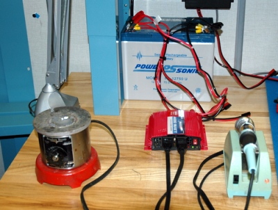
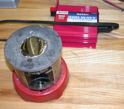
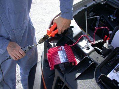
For the load test, I connected a 320 Watt solder pot, and a 60 Watt solder iron. A good resistive load for the 400 Watt inverter. Worked fine for a couple of minutes, then shutdown. A yellow light indicated "input fault". The manual described this condition as overheating. Hmmm. This inverter was very quiet. The fan wasn't working. Does this fan run constantly when the inverter is powered up, or does it have a thermal switch and only runs when it hits a certain temperature?
The initial test setup that discovered the fan issue.
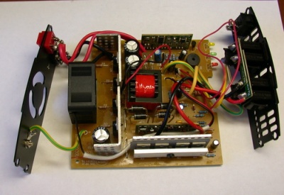
I removed the 4 screws on the front and back of the inverter, and pushed all the guts out of the case
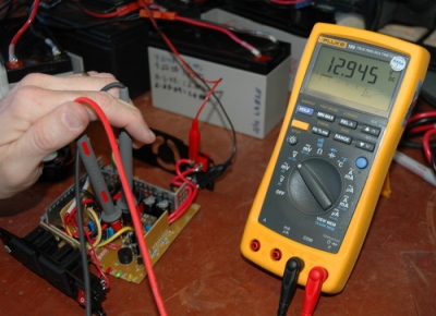
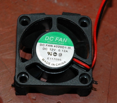
Being very careful, I connected the inverter to a battery, then used a meter to measure the fan wires where they connect to the circuit board. I then powered up the inverter, and discovered the fan receives power when the inverter is powered up. It SHOULD be running. The fan spins by hand, so it's not bound up. Wires look fine. Bad fan.
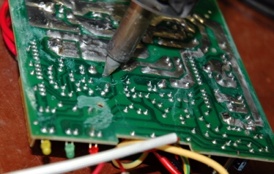
I've got an expensive solder station, but it isn't necessary. A basic soldering iron and a piece of copper braid will also remove solder.
The original fan now removed.
I went online and found a replacement. Similar specs. About $8.00
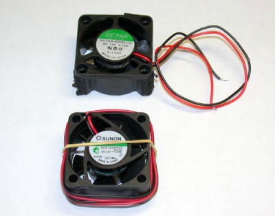
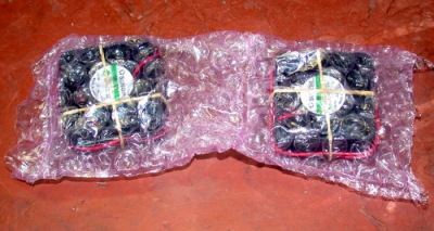
Got a couple more spares just in case. I don't expect the replacement to fail, but the original in my other Vector inverters might.
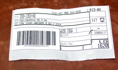
I found it at Digi-Key. P/N 259-1353-ND
A little flux, then soldered in the new fan (bottom two connections).
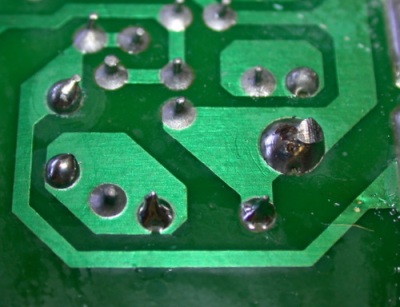
After bench testing to verify the fan now works, the inverter was reassembled, then load tested again. I left it running for about 20 minutes with the 320 Watt solder pot. Note the molten solder. The case on the inverter remained cool, and the fan is humming quietly, moving plenty of air.
Now the inverter is ready for field use once again.
So once again we show if you don't test it, it doesn't work. I now plan on LOAD testing all my inverters to verify they do what the manufacturer claims. This inverter worked fine with light loads. But soon failed when it was loaded near its capacity.
Hopefully this article also showed that you don't have to have a schematic or degree to fix complicated things. This failed due to a basic component, and took very little to fix it. Many things in life are this way. Give fixing things a try. You'll either succeed, end up with some spare parts for another project, and/or might learn something in the process. Worst case, delay throwing away a broken widget anyway.
2manytoyz
www.alpharubicon.com
All materials at this site not otherwise credited are Copyright © 1996 - 2009 Trip Williams. All rights reserved. May be reproduced for personal use only. Use of any material contained herein is subject to stated terms or written permission.