*Old Time Windmills*
By: ReadySet
12 October 2009
There is something peaceful about old windmills. Maybe it is the slow rhythmic creaks and groans as they turn in a gentle breeze on a summer afternoon that reminds one of less hurried days gone by. But despite the nostalgia, a closer look at these windmills reveals a high level of engineering and clever design.
Background
Around 1900 the windmill industry was big business in the northern Midwest. This was before electricity made it to the farms. Muscles (human and animal) provided most power needs. Cars and tractors were just starting to replace horses. As always, having a reliable supply of water was very important. Many water pumping windmills were built to satisfy this need nearly effortlessly. Windmills were also used at this time by the railroad. The mills pumped water into holding tanks so it was ready for use when a steam engine came by. Windmills came in a variety of sizes to meet various applications. The diameter of the rotors varied from 4 ft to 22 ft.
Mid-America Windmill Museum
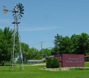
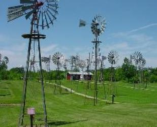
Just east of Kendallville, Indiana is the Mid-America Windmill Museum. They preserve and display many mills that were made locally. Although only a few do actual work, the scene is quite kinetic as most are free to turn in the wind.

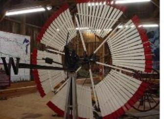
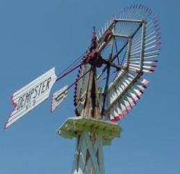
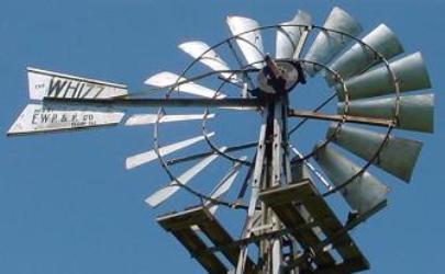
Wood and steel were the dominant materials used on these mills. All the steel units (and many of the wood units) in the museum have a vane to keep the rotor turned into the wind on the upwind side of the tower. The vanes (tail feathers?) are movable and can swing out to the side to stop the mill from turning, as shown in the picture above.
An interesting variation is a “vaneless” design, where the rotor is on the downwind side of the tower. In this position the wind automatically pushes the unit to the proper position for best power. See picture below, left.
High Wind Protection:
Many windmills had some form of overspeed protection. The vaneless mills had this automatically, as the geometry is such that high centrifugal force pushes the vanes to the parked position. When the wind dies down, a weight brings the vane sections back to the normal operating position. Several wood windmills used a side vane to steer the unit out of the wind, as can be seen here:
The mill in this picture is stopped or furled. The large vane is held to the side by a winch at the bottom of the tower. In operation the winch is released and a weight swings the vane to the run position. Notice the smaller second vane. It is permanently mounted on the side just behind the rotor. When the wind gets strong, this vane turns the rotor out of the wind. The large vane is free to swing to the position shown, but must lift the weight to do so. In the end, the forces balance out and the windmill turns out of the wind far enough to prevent damage.
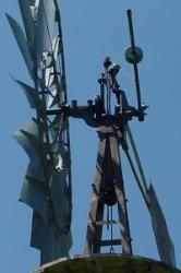
Several steel windmills in the museum have overspeed protection that use a variation of the side vane approach. These have the axis of the wheel offset from the center of the tower, as shown here
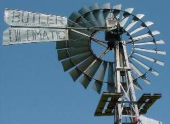
This geometry combines the side vane with the wheel itself. High winds cause the wheel to turn out of the wind. This turning force is countered by a spring or weight on the tail that tries to keep the windmill facing into the wind. It is likely that a great deal of experimentation went into finding the right combination of rotor size, vane size, and weight or spring force.
Crank Construction
Several approaches were used to convert the rotary motion of the vanes to the up and down motion sent to the pump. Some were quite clever and simple. All the windmills shown above use a simple crank assembly, where the top of the crank moves along vertical guides. Occasionally the crank arm was made of wood. The bearings in older units were sometimes made of Babbitt metal or oil soaked maple wood, and were often out in the open, subject to wind, dirt, and rain. Oil soaked felt was a common way to lubricate these bearings. This required the farmer / rancher to climb the tower every week and re-oil the felt.
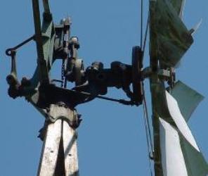
Over time significant improvements were made in lubrication. Chief among these are the “self oiling” units that reduced maintenance intervals from weekly to yearly. Perhaps the most common approach turned out to be gears running in an oil bath as shown below:
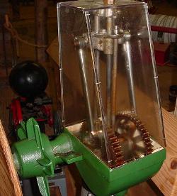
In this demonstration model, the windmill rotor is on the left. It turns a shaft with small gears inside the housing. The small gears turn large gears that run through an oil bath at the bottom of the housing. The crank arms then move an assembly up and down the vertical guide rods. In this picture is a 3rd vertical rod (smaller and more rusted than the others). This is a small oil pump that squirts a bit of oil onto the vertical guides every revolution. Now you know why the gear housing cover is shaped so strangely!
Power Mill
The museum has an unusual windmill called the Power Aermotor, made by the Aermotor Company. In this unit, the output shaft rotates rather than moves vertically. From a plaque at the museum:
“… This mill was designed to power feed mills, saws, corn sheller’s and other light machinery. It was introduced in the 1880’s and was around until the1930’s.”
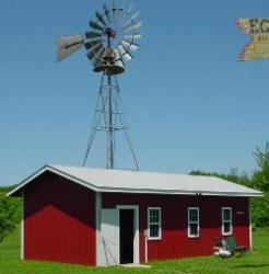
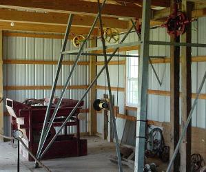
This museum display is set up so that the windmill drives a line shaft in the shed. (See top of picture on right.) Looks like a nice way to get some work done on a chilly and windy winter day!
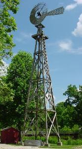
Perkins Windmill
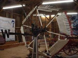
One last windmill deserves mention. The Perkins windmill company was in operation in Mishawaka, IN from around 1870 to 1925. One of these windmills is located in the Bonneyville Mill County Park near Bristol, IN – you saw this in the opening picture above. Another unit is on display at the Mishawaka Public Library:
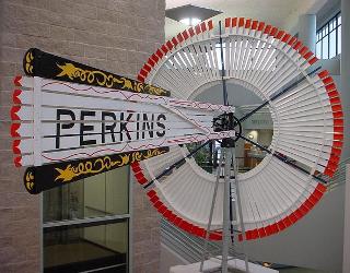
This wood mill was noted for the ornate decoration on the tail and bright color scheme on the wheel. Overspeed protection is accomplished with an offset rotor, similar to many steel mills. This close-up display of a 10 ft (diameter) unit allows a good look at the mill’s construction:
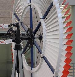
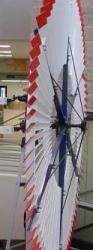
Building a working unit might not be terribly difficult with some clever improvising for the crank. (Does that hub look like a car’s disc brake rotor?)
Conclusion
These relatively low tech windmills demonstrate excellent engineering and general cleverness to solving life’s important needs of water and power. The technology is fully developed, has been tested over many years of actual use, and continues to be available today. It is entirely feasible to return to these windmills should the future provide us with less hurried days once again
ReadySet
www.alpharubicon.com
All materials at this site not otherwise credited are Copyright © 1996 - 2009 Trip Williams. All rights reserved. May be reproduced for personal use only. Use of any material contained herein is subject to stated terms or written permission.