*Portable Solar Panel Array Brackets*
By Blizzard
01 September 2003
We needed a "portable" bracket for our Siemen solar panels. Since we might be moving shortly, I didn’t want to permanently mount them on the roof. Additionally, I wanted to make them "modular" so I could add and remove panels from the sub-arrays (to put on my pop-up camper, for example), and add additional arrays to the system (more power – YES!). The panels also had to be adjustable to maximize the sun exposure since we live in the valley between two mountains and have a limited amount of direct sunlight.
I pulled the brackets from the primary system in storage only to find out that Solarex 77 and Siemen 75 panels are different sizes. I could, however, use the brackets as a template. In doing so, I also discovered the system in storage was missing all the hardware to mount it on the roof. Ahh, facta non verba strikes again.
We searched for standard aluminum stock to manufacture the new brackets. There was no u-channel available anywhere so the brackets were made using 2" angle aluminum. Here is the parts list:
(4) 2" x 2" x 8’ aluminum L shaped stock. (Cost: $64.00)
(16) ¼ " x ¾" bolts with Ny-lock nuts for mounting the panels (4 per panel, 4 panels = 16)
(18) 5/16" x 3/4" with Ny-lock nuts and "fender washers to attach the unit to the frame and posts
(8) 5/16" x 1 ½ " Lag screws for mounting to the wood
(1) 2" x 6" x 8’ Treated lumber
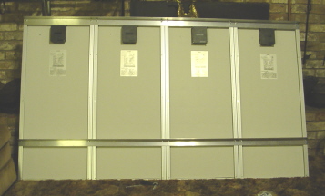
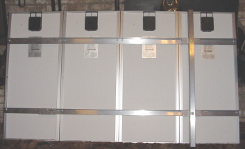
Here is the initial design idea.
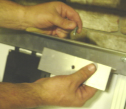
Drilling holes was an interesting task. The spacing between panel holes, and between the panels themselves is really non-standard. Measuring from the outside edge of the panel, the first mounting hole is 7/8" from the edge. The hole on the other side is 19 15/16" from that first edge. Metric conversion didn’t improve things so I drilled a "template" in 1" steel to keep my spacing correct. That meant I didn’t have to drill pilot holes in an effort to keep everything aligned – just slid my template made up of 3 properly placed holes into position. You drill the initial hole, place a bolt through the end hole of the template (the hole you just drilled), and drill the next 2 holes. Then, pull the bolt and template together and place the bolt in the last hole drilled. I just kept sliding down the bar until I had 8 holes drilled. The panels fit like a glove.
The next step is to trim off the excess from the end where you drilled the last hole (should be about 12" left – to be used later). I used a metal cutting disk then took a file to the end of the aluminum since it was quite sharp. I flattened the cut then beveled the edges so I could run a hand around it without cutting myself.
Now, repeat the above process until you have 2 horizontal matching bars for 4 panels (or however many you are mounting). Mount them with the ¼" bolts and ny-lock nuts.
Oops, while the top bar is flush with the top of the panels, it wouldn’t provide full range of motion needed for seasonal adjustments so I moved it down to the next row of holes on the panels.
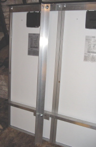
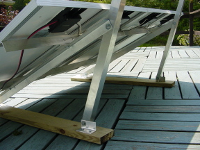
The next step is the attachment points for the vertical supports. Remember the leftover 12" extra piece from the horizontal support bars you just attached? Well, cut the 2 scrap pieces in half, leaving four 6" pieces and file the edges. Remove the horizontal pieces from the panels. Place the 6" pieces so they provide a face for the vertical supports, equidistant from the end of the horizontal bar. I decided to form them into a u-channel. In retrospect, it would have been easier just to place them on top of the horizontal support, forming an s-shaped bracket. Drill two holes 3" apart to secure the bracket, and one hole in the center of the adjacent side to mount the vertical bar. Now reattach the horizontal bars to the panels and attach the vertical support brackets.
Next, cut the vertical supports. I just cut an 8’ piece in half and filed the edges. I measured the holes between the 2 vertical support brackets, and drilled corresponding holes in the vertical bar. Additionally, you drill holes on the adjacent side, on top and on bottom. Space these in ¾" from the top (or bottom) and side of the piece. These will provide your array angle support on top, and your foot attachment on the bottom. If you don’t space the holes to the outside of the bracket, the horizontal support will bind when trying to adjust it.
Note: Here is where I figured out I had to move the top horizontal bar – oops. Even with moving the attachment holes ¾" from the edge, it still bound up. By moving the horizontal bar down, I had full range of movement.
Attach the vertical bars to the horizontal brackets using 5/16 bolts and fender washers.
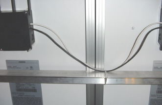
With both horizontal bars and vertical bars attached, it is time to start the wiring. I decided to use 10 gauge zip wire and "powerpole" connectors. These are obtainable from http://www.powerwerx.com. I am sure there are cheaper sources out there, but I couldn’t find any conveniently. These connectors also allow attaching another sub-array or disconnecting the array and moving it inside for bad weather or to prevent theft.
See Warlords article on wiring solar panels if you have further questions about this process. ../restricted/altenergy/two75wpanels.htm
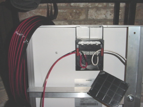
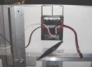
Then, zip-tie the wires so they don’t flop in the wind and also drip away from the electrical boxes.
Now comes one of the hard parts – calculating the angle for the panels. For maximum efficiency, the panels need to be perpendicular to the sun. During summer solstice, the sun is 15 degrees higher in the sky then the spring/fall equinox. During winter solstice it is 15 degrees lower. So, start by figuring the latitude of your location. In the continental US, it will be somewhere between 25 and 50 degrees (give or take). That number is the angle from horizontal you want your panels set at for spring and fall. Add 15 degrees for winter, and subtract 15 degrees for summer.
I cut four 3" feet off the end of the remaining piece of stock aluminum, then cut the remainder in half. After filing down the edges, I mounted the feet using two 5/16" lag screws into pieces of a 2" x 6" x 8’ treated lumber I had cut in half. The attachment points for the adjustable arms are ¾" from the edge for both the foot and the adjustment points. Again, if you place the holes in the middle of the bar, you will bind as you take the panels through there full range of motion.
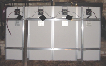
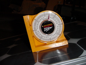
I used a angle locator (shown below) to determine the exact panel angle. You can also use a simple protractor and level.
We measured the panels for latitude, latitude plus 15 degrees, and latitude minus 15 degrees. Then we drilled the corresponding holes in the adjustable arm. In our case, we didn’t trim the excess from the top of the arm is case we move further north and need the length to increase the array angle.
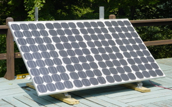
And there you go – a completely portable, adjustable panel array for your alt power needs.
Blizzard
www.alpharubicon.com
All materials at this site not otherwise credited are Copyright (c) 1996-2003 Trip Williams. All rights reserved. May be reproduced for personal use only. Use of any material contained herein is subject to stated terms or written permission.