*Understanding Alternating Current*
By Kingpin
Some more power concepts
Many people that work with solar power have a grasp of the idea that Power = Volts x Amps.
This is true for DC power. When you use AC, things are not quite that simple.
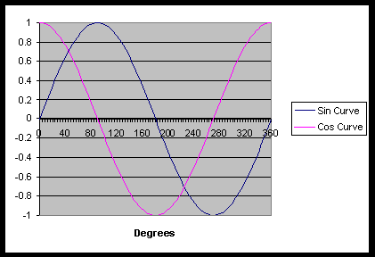
With Alternating current, the voltage varies sinusoidally.
It is still true that Power = Volts x Amps, but this is only true instantaneously. Thus the power at any one moment in time is equal to the Volts at that time multiplied by the Amps at that time. If we want to find the average power used, then we must take the average of the power at each time interval. Mathematically this is known as Integration.
The integral of a sinusoid over one full period is zero, because there is as much time spent below zero as above it.
Power is equal to Volts x Amps, and so the average power produced will be equal to the averages of the products of the instantaneous voltages and currents.
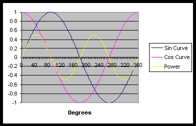
In this graph, we can see that the power (the yellow line) fluctuates sinusoidally. In fact, it forms a sinusoid of double the frequency of the Voltage curve. The power goes positive and negative, with an average value of zero.
 +
+
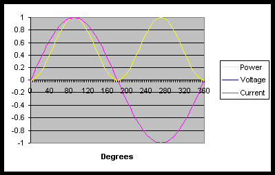
In this graph, the Voltage and Current are in phase [i.e. they rise and fall at the same time], and so the power looks like a sin2 graph. This is positive only, so the average power is positive.
What does this mean? In the first graph, power is flowing in and out of the system, without being used up. In the second, power is flowing into the system, and being used up.
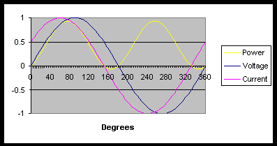
This graph is much more like what you would see in the real world, if you measured the voltage and current across your washing machine. Here the voltage and current are 30 degrees out of phase, and so the power will have positive and negative parts, but in total the average power used is positive.
This makes sense, after all. Your washing machine does use power. But why are the current and voltage out of phase with each other?
In electric motors (and many other electric equipment), force is generated through electromagnetic fields. Creating these fields requires the use of coils. A coil has a property known as inductance. This is similar to turning a pedal on a direct drive wheel. Initially it requires a lot of force to turn the pedal, but then once you get it going, the pedal will drag you along if you stop pushing. What happens in an inductor is quite similar. A voltage applied across an inductor applies force to the electrons sitting in the wire. They start to move, but because they have their own electric field, and due to the geometry of the coil, they impede each others movement. As time goes by, they begin to move faster and faster, and the current increases. Thus if a DC voltage is connected across an inductor, the current will increase [indefinitely with ideal components].
Therefore in a system with an ideal inductor, the voltage and current will be 90 degrees out of phase. Because the current increases after the voltage increases, the current is said to lag the voltage.
In the real world, there is both resistance and inductance in your washing machine coils, and so the voltage and current will neither be in phase nor 90 degrees out of phase, but somewhere in between. As you can see from the graphs, the less the lag, the more the delivered power, while the greater the lag, the lower the delivered power, until at 90 degrees of lag, there is no power delivered.
In order to be able to describe the power used by a system, it is convenient to split the power usage into two components. There is the ‘Real’ component, which is the average power used by the system, and the ‘Imaginary’ component, which is the power that comes in and out of the system, but has zero average value. The maximum amount of power that your generator or inverter needs to supply is equal to the Real Power plus the Imaginary Power.
The Power Factor of your system is the cosine of the angle between the current and the voltage. A power factor of close to 1 means that the voltage and current are close together. A low power factor will mean that your voltage and current are far out of phase.
If you are running a factory, or using large amounts of power, you will be charged extra by the power company if your power factor is low. Although the amount of real power that you are using does not change, the more imaginary power that you use, the more current the power company has to send through the hundreds of kilometers of wires to you. This produces losses for them in their wires. Obviously they will recover this cost by charging you more. You can correct this by installing power capacitors across your power supply, and ‘producing’ your own imaginary power. Unfortunately the power company won’t pay you for any imaginary power you produce for them!
RMS
RMS stands for Root Mean Square. It describes a procedure for finding the average value of a voltage.
When you have a value varying sinusoidally, the average value will be zero. If we want to know the amount of voltage that an equivalent DC system would have to output to give the same power level, we need a method that will take into account that power is proportional to the square of the voltage.
To calculate the RMS value, we take our voltage, V. We then square it: V2.
We now take the average of the squares of the voltage measurements. [Or integrate the curve and divide by the period]
We then take the square root of the average value. This gives us a voltage.
For example, here in SA, we have a 220 volt mains supply at 50 Hz.
The RMS value of the mains voltage can be calculated as follows:
V = A sin(wt) Where A is the amplitude, and w is the angular frequency.
Angular frequency is measured in Radians per Second. In order to convert Hertz (cycles per second) to Rad/s, we use the fact that 1 cycle = 360° = 2p radians.
So w = 2p f = 2 x p x 50 = 100p Radians/s
So V2 = ( A sin(100p t))2
= A2 sin2(100p t)
So  V2dt = A2 sin2(100p
t)dt
V2dt = A2 sin2(100p
t)dt
Now cos(2wt)=cos2(wt) – sin2(wt), and knowing that sin2(wt)+cos2(wt) = 1,
cos(2wt)-1 = -2sin2(wt)
So sin2(wt) = (1-cos(2wt))/2
So V2dt = A2 (1-cos(100p
t))/2dt
=A2/2 1-cos(100p
t)dt
=[A2/2(t – 1/(100p ) x sin(100p t)) ]
We are integrating over one period. A period is one full cycle, or 2p radians, so we evaluate the integral between 0 and 2p . In the time domain, this is 1/50 seconds, so we evaluate between t = 0, and t = 1/50
A2 /2 x( ((1/50) – 1/(100p ) x 0) – ( 0 – 0) ) = A2/100
So the Mean of the Square is equal to the integral divided by the period.
So MS = (A2/100) / (1/50) = A2 / 2
Then the RMS =  MS = (A2/2) = A / 2
So if the value of your power supply is 220 volts RMS [as it is in SA], then your actual voltage is about 310 volts.
If you are in the US, then your RMS value is 110v, and the actual peak voltage value is about 156 volts.
I apologise for the complex maths used above. In order to derive the calculation for RMS to Peak voltages, it is necessary to use a certain amount of mathematics. The essential point is that for sinusoidal power supplies, the RMS voltage is 1/2 of the Peak value.
Thus if you are adjusting a homemade transformer and measuring the output with a multimeter, ensure that you remember to calculate the correct RMS value. Failing to do so can result in you supplying too low a voltage to your system. For a 110v peak value, the RMS voltage will be about 46 volts. This can cause problems with most of your electrical systems. Fancier voltmeters have an RMS option that will give you the actual RMS value. Just remember to check that this is what you are measuring.
Kingpin
All materials at this site not otherwise credited are Copyright (c) 1996-2002 Trip Williams. All rights reserved. May be reproduced for personal use only. Use of any material contained herein is subject to stated terms or written permission.