*The Xantrex 458 Inverter/Charger and the Link 1000 Controller*
The Xantrex 458 inverter/charger is a unit that I picked for my alternate power application because the general consensus among consumers who have used it was that it is a very durable unit and the company has a very solid technical support staff. I can personally attest to the fact that the company has one of the best technical staffs I have ever encountered. I felt like I was talking to an electrical engineer when I called to make sure I had the correct understanding of what this system could do. The unit is very expensive in that new it cost about $1000. However, at the advice of a Rubie, I found a new one on ebay for $475. It had been installed but never used so I lucked out. The Link 1000 controller was around $150, the 4 batteries are Everstart model 27DC-6 at $53 a piece and the other items needed were stranded number 10 wire, inline 2 amp fuses for the Link 1000 controller, a Cooper/Buss inline 150 amp breaker to go between the batteries and the inverter and 2 and 4 gauge battery cables. I also installed a sub panel for the items in the house that would be powered by the battery bank.
The Xantrex 458 comes in several different offerings, but the unit I have is model 20-12. This means it has a 2000 watt capacity, has one AC input, one DC input, and two AC outputs. It uses the AC input to charge the batteries while simultaneously sharing power with all the items that are connected to the battery bank. For example, as long as the power is on from the power company, or as long as the breaker is turned on, the inverter will charge and then float the batteries, as well as share power with the sub panel through the two AC outputs on the unit. Additionally, if the power fails, I can use a generator to charge the batteries without having to make an special connections as I could simple crank it up and connect it through my detached garage sub panel which has a 60 amp rating and will back feed into the house main panel. This 458 model has a 3-stage 100 amp battery charger which has proven to be very efficient. The 458 also has a built in power switch that converts to battery power automatically as soon as power is lost from the main panel. In that respect it acts as a UPS.
The installation is a bit tricky and I am not an electrician but I’ll try to explain the best I can. The new electrical code requires that in a main panel the neutral and the ground be permanently bound, or connected. That is, if you look inside you will see that the ground and the neutral bars have a jumper that goes from one to the other and makes the connection. In order for a system like the 458 to operate correctly, the load side (the items that are being fed power by the inverter) of the inverter that has the two AC outputs must be feeding a panel or individual outlets that have the ground and the neutral separated. I am somewhat familiar with this arrangement because I work in a laboratory and all of our precise instrumentation must be on individual circuits with an isolated ground. The outcome of this type of arrangement is less interference from unbalanced loads. In order to achieve this on the sub panel I had to remove the jumper that was already installed on the sub panel when I purchased it from Home Depot. As a side note, I used the same make sub panel as my main panel so the breakers are interchangeable.
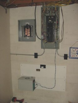
The first thing I did was install a wood backing on the concrete blocks directly below my main panel. I then installed my sub panel. The AC input side of the inverter needs to be on a 30 amp breaker coming out of the main panel. The input in this particular model of the 458 must be on only one leg of the main panel. That is, because it only has one AC input, that input must come from only one side of the 30 amp breaker. Additionally, the output on the inverter needs to be separated so that it goes into two separate sides on the sub-panel. That is, one AC output goes into the left phase and the other AC output goes into the right phase and it is vitally important that you don’t use a breaker that joins both sides for 220 volt. That is, only one phase (one leg) of the power being supplied from the inverter can be used. It cannot be used to supply a 220 volt application. In short, don’t use a breaker that connects both sides of the sub panel. The 458 has an external ground and an internal ground. The external chassis ground connects to the main panel’s grounding block and the internal ground goes to the isolated grounding bar in the sub panel as well as the main panel’s ground bar.
So far I have run loads that reached 120 amps during a 4 hour period from the battery bank and inverter; the start up amps have been over 250. This includes the fan on the air conditioning unit, not the external compressor (I have natural gas heat so if the gas is flowing I’ll have my regular heat in the winter, if not I have a wood stove), an upright freezer, an outlet circuit with computer equipment, our primary refrigerator and two lighting circuits. The idea behind this system is to run the essential components in the house if the power fails and use the generator to recharge the batteries until I have an operational solar system. I have yet to purchase and install the solar panels as that will be phase two of this project. I’m going to be some test to see how long this system will run these items and I’ll adjust my load accordingly.
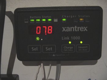
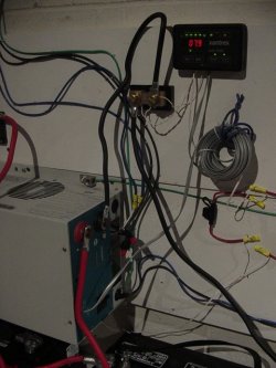
The Link 1000 is essentially a more sophisticated monitoring system that allows the user to program the size of the battery bank, type of batteries used, the power sharing ratio, idle settings that starts up the inverter at a pre specified amperage load, automatic equalization of the batteries by activating that feature and up to 16 advanced features including the ability to monitor another battery bank. The Link 1000 also monitors the battery status, current voltage, amperage, amp hours consumed by the inverter, time remaining until the discharge floor is met based on current consumption, or an average consumption over a specified period of time, battery history, and a battery capacity test. The link 1000 is a push button system that I’ve found to be easy to understand and operate. A shunt is used to monitor the amperage ratings and requires a common negative distribution lug. This was supplied with the unit. In the picture below the shunt is located at the 7 o’clock position to the LED monitor and has an incoming negative black wire and one going to the inverter.
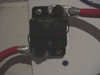
This HI-AMP fuse/breaker was used to protect the batteries in the event of a short circuit or overload. During the period I was drawing 120 amps from the batteries this device became heated, but not too hot to touch. It has a re-settable breaker. I found this device at Auto Zone and it’s rated for RV/marine use as it is waterproof. It was $26, but is much cheaper than a comparable fuse block with the same amp rating and can be reset whereas a fuse can not.
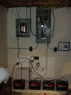
The sub panel on the left has an isolated ground that is connected to the cold water pipe which is connected to an earth ground. The main panel on the right is unchanged and meets NEC code. Notice the single number 10 stranded wire going to the inverter/charger and then to the sub panel from the inverter/charger. I choose to use this wire because I had it on hand.
My next project will be to have a separate inverter and battery bank to be used with the solar panels. If I can figure out how to use the Xantrex 458 with the solar panels, I will update this article.
JYWolfe
www.alpharubicon.com
All materials at this site not otherwise credited are Copyright © 1996 - 2006 Trip Williams. All rights reserved. May be reproduced for personal use only. Use of any material contained herein is subject to stated terms or written permission.