*2007+ Jeep Wrangler Rubicon Locker Modification*
Background:
Make model: Jeep Wrangler Rubicon (JK series) 2007+
Experience:
I have been running this modification on my own Jeep Wrangler for the last 12 months with NO problems. Facta non verba.
Purpose:
This allows you to use both lockers in all transfer case modes by providing a ground for the relays.
Requirements:
Disclaimers:
By undertaking this modification you are potentially voiding your drivetrain warranty. While Jeep dealerships have traditionally been very lenient on modifications, they do vary. Bear in mind that activating this modified system on hard dry pavement has the potential to destroy you axles, transfer case, differentials - especially around curves and can cause your vehicle to crash or roll over due to all 4 wheels being 100% locked together with no room for slippage. Now that that's out of the way, onto the lockdown.
Overview:
You are creating a bypass to ground circuit to allow your locker relays to activate regardless of transfer case position or TPIM inputs. While this will allow you to destroy your differentials, transfer case, or axles on dry pavement - it is designed to allow you to operate your lockers when not in 4WD-Low. This can be useful in sandy environments, high-speed mud running etc. This system does not disable the factory system. It will operate different from the factory system. Under normal operation your locker indicator lights will remain solid during operation. With this bypass, your locker indicator lights will blink until disengaged. (see diagram below)
Procedure:
Remove the battery by disconnecting the positive, then the negative post clamps. Then remove the battery hold down bracket with an 8mm socket. (I've been told other sizes are used as well).
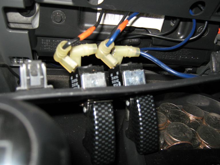
Locate the locker relays on the passenger side of the vehicle right next to the battery on the fender wall. Here is what a picture looks like of the relays.
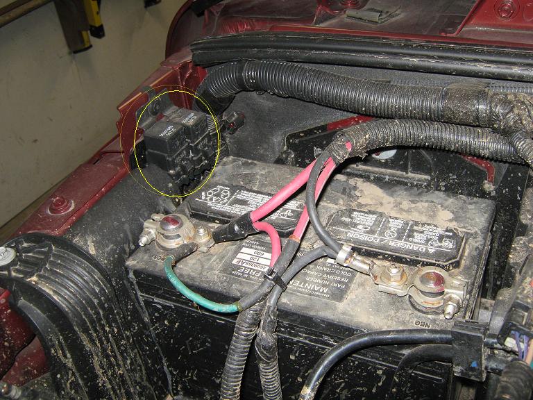
Now locate the plastic rivet holding the relay bracket to the fender-wall and loosen the rivet until the relay mounting bracket comes loose. Pull as much slack as possible on cables and lay them into the empty battery tray area.
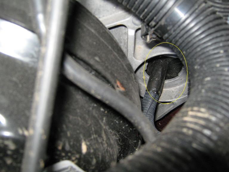
Locate the ground wire coming out of the relay from the bottom.
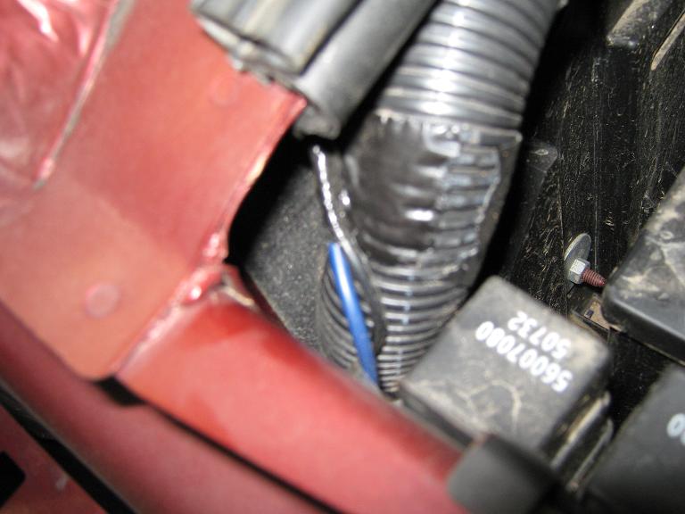
Solder 1 of your wires to each ground coming out of the relay (I tried wire crimps first but they did not work well for me). Repeat for the other relay. Tape and heat shrink your solder splices well, this area of the engine compartment gets a healthy dose of mud (see pictures). Tape ends of looming to prevent wires from being seen, or coming loose due to vibrations.
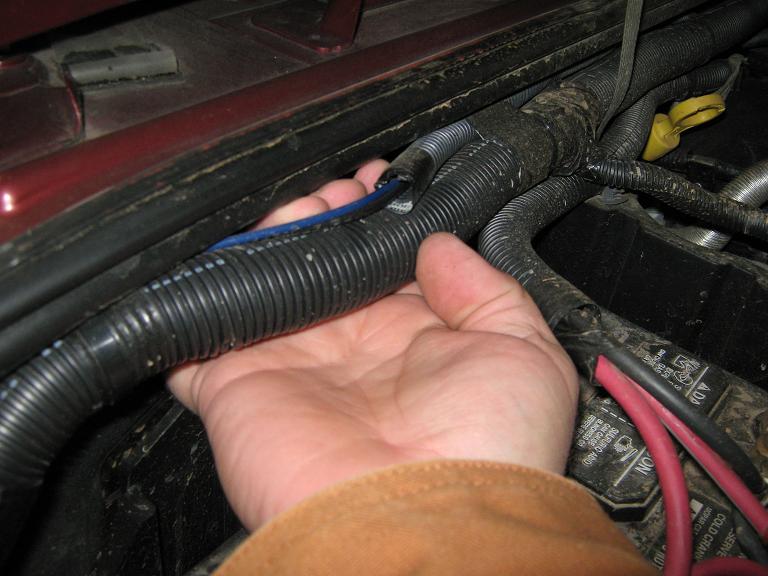
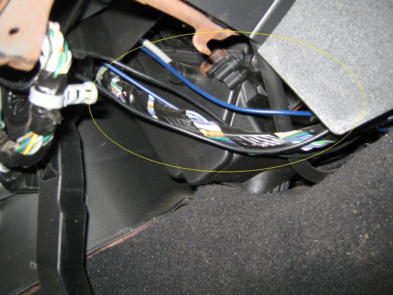
Mark each & run your cables through the looming and feed the wire loom across the engine compartment from the relays to the drivers side of the vehicle. If you don't like answering dumb questions from your dealership regarding the extra wiring, you will take the time to dress it up and tuck the loom behind the OEM harness (see picture).
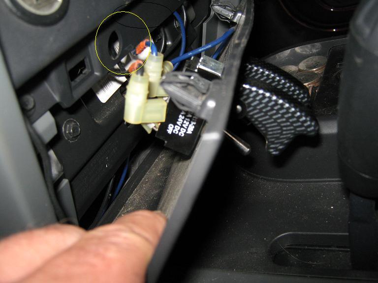
Run your wire loom through the firewall using the existing grommet near the steering column, and into the passenger compartment.
Once your wiring is inside the vehicle dress your cabling accordingly (not like mine).
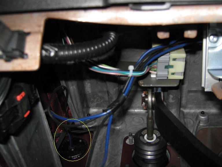
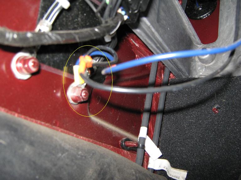
Run (2) cables from your switches to the ground nut near the drivers side door harness.
Run your 2 wires from the relays to the switches.
Connect each relay and switch separately using your marked cables (you did mark them didn't you).
Individual placement and switch type can vary, basic single pole switches are the minimum with lighted and/or a single switch being other options (not recommended K.I.S.S.)
I chose to mount my switches in the unused panel below the 12VDC power outlet and cigarette lighter.
Careful placement in this location is advised due to tight clearances (read: no clearance) behind the panel. I had to bend the tabs on my switches to push the panel closed.
Testing:
Loosely replace the battery and tighten the battery post connectors. Key the ignition to "ON" and flick 1 of the switches. If wired correctly the locker indicator lights should flash on the instrument cluster. If no locker indicators come on verify you have a good ground at the drivers door nut (might need some paint scraped off). Double check your wiring connections.
The finished product looks clean and operates exactly as I intended.
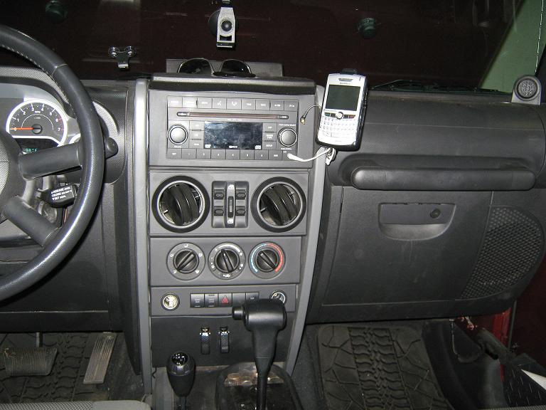
The advantage to this configuration is that I can engage one or both lockers when needed (evasive maneuvers over obstacles or through crud) on less than ideal surfaces and up to any speed.
Once you've got the switches working correctly, close up the dash panel, remount the locker relay bracket, and reinstall the battery securely into the tray. Drive to your local mud hole and get thoroughly stuck, then flick the switches and marvel at your resourcefulness. After 60 days, check ground connections, and wire looming are secure. Find a loose surface and test monthly, get familiar with the handling changes.
www.alpharubicon.com
All materials at this site not otherwise credited are Copyright © 1996 - 2008 Trip Williams. All rights reserved. May be reproduced for personal use only. Use of any material contained herein is subject to stated terms or written permission.