*How To Build A Voltage Regulator Circuit*
We take for granted that the grid is available, and plug all our wall warts into the various outlets to charge up our widgets. When the grid does go down, how do you charge these items then? You could use a battery with an inverter to convert 12VDC to 120VAC, then plug the wall wart (plug in transformer) into the inverter to take the 120VAC and bring it down to 5VDC, 9VDC, or whatever your widget requires. But each step in the process creates losses. Not to mention the frustration of having to go setup the equipment for this purpose when the lights go out.
There's an easier/better way. For many items, they require 12VDC or less to charge. A simple voltage regulator can be made with a few inexpensive parts. This will enable you to plug your widgets into the battery bank directly. They will always be charged, no matter what the grid is doing. This also reduces the parasitic load on your electric bill from wall warts that stay hot and waste energy. Some items require more than 12VDC to charge. We'll discuss that towards the end of this article.
The item I chose for this example was an LED worklight purchased at Harbor Freight. No cigarette lighter adapter provided.
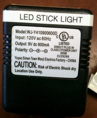
All the necessary information is usually right on the wall wart. 9VDC, 600mA, center pin positive.
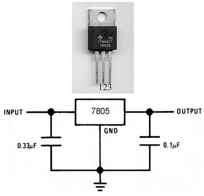
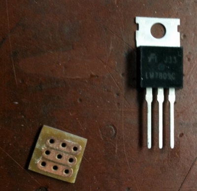
There are a series of voltage regulators that require very little hardware to complete. The LM7805 (pictured) is a +5VDC regulator. The LM7809 is a +9VDC regulator. Many other sizes available, but these may be the most common for your application as well. They are wired exactly the same, for either regulator. Pin 1 is the input, Pin 2 common ground, Pin 3 the output. A 0.33uF capacitor is connected between the input and ground, a 0.1uF capacitor connected between the output and ground. I "have" wired these up without the capacitors in the circuit before without issue, but doesn't take much effort to put these in and it avoids any potential noise issues later.
Here's the info from the spec sheet:"The LM78XX series of three terminal positive regulators are available in the TO-220 package and with several fixed output voltages, making them useful in a wide range of applications. Each type employs internal current limiting, thermal shut down and safe operating area protection, making it essentially indestructible. If adequate heat sinking is provided, they can deliver over 1A output current. Although designed primarily as fixed voltage regulators, these devices can be used with external components to obtain adjustable voltages and currents."
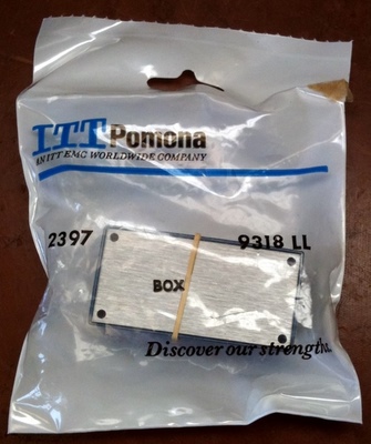
I prefer Pomona brand project boxes. They aren't cheap, but they'll last forever IMHO. You can find project boxes at Radio Shack also. Just make sure part of it is metal as we'll use that as a heat sink.
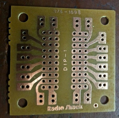
You could connect the capacitors and wires directly to the legs of the voltage regulator, but a generic PCB from Radio Shack makes this a bit easier.
I've cut these boards with a bandsaw before, but used a nibbler instead this time. When I got close to the size needed, I used a piece of sandpaper to finish the removal of the unnecessary portion of the board. I trimmed away the excess copper circuit with an Xacto knife.
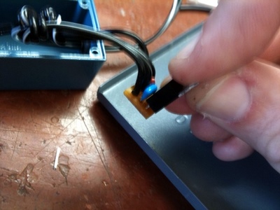
The input/output wires were fed into the project box, and I tied a figure 8 knot onto each cable as a strain relief. All the components were soldered onto the board.
The regulator is at the top, a capacitor goes between the input and ground (pins 1 & 2), another capacitor on the output (pins 2 & 3), and the wiring is attached (1 input, 2 ground for input and output, 3 output).
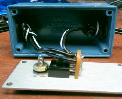
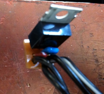
The back of the voltage regulator is a metal plate. This is used to dissipate heat. These little regulators are good up to 1 Amp, but require a heat sink. The regulator was bolted to the lid of the project box. The circuit board weighs next to nothing, and the legs of the regulator hold it perpendicular to the lid, away from potentially shorting out. In this picture there's a better view of the strain relief knot in each cable. A grommet was placed in each hole to prevent the wires from chaffing.
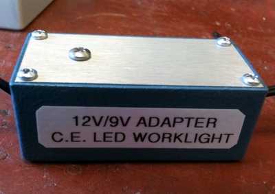
The box is closed up, and a decal was added so I know what project this box belongs to.
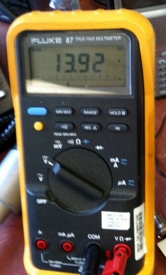
Okay, time for a test. Input voltage from the battery 13.92VDC.
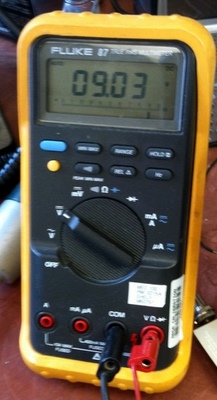
Output from the regulator circuit, 9.03VDC.
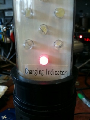
Worklight plugged into the battery bank, charging.
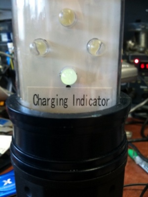
A little while later, green light, fully charged.
This is definitely a DIY project. Basic soldering skills are needed. The parts are cheap. The 9VDC regulator was purchased from Digikey. P/N: LM7809CT-ND, Link to the item. Only $0.43 each.
The 5VDC regulators I purchased also came from the same company, also $0.43 each. P/N LM7805CT-ND,link to that product. The input capacitor can be found at this link ($0.46). Be warned, this is a tantalum capacitor and is POLARITY SENSITIVE. If you put it in backwards, it will burn up! They are clearly marked. FNV, been there, done that. It's amazing how much stink such a little item can release! This was many years ago when still learning electronics... The output capacitor can be found at this link ($0.11). Shipping will cost more than the parts, but Digikey is my favorite online electronic parts place. Reliable, quick, competitive pricing. Customer service is A+.
The actual hardware needed is under a $1. Get whatever project box that suits your needs, the Pomona one was $9. Radio Shack ones will work too. You can cut the plug from the existing wall wart, or get a replacement one for ~$1. I prefer to leave the wall warts intact, giving me the option to use them if needed. I highly recommend adding a label to the wall wart, and the project box so they can be easily identified later (what's this go to?).,/p>
If you need a DC supply higher than your source (i.e. 12VDC to 18VDC), there are off the shelf products for this purpose. These are DC-DC converters. They allow products like laptop computers, which often have > 12VDC batteries these days, to charge from an automobile. Powerstream sells these for under $20. Just take note of the efficiency rating. The product I researched was rated at 50-80% efficient. I might use one of these periodically in an emergency, but might not on a day/day basis. I would be particularly interested in the parasitic load once the item is fully charged. I plan on buying a DC-DC converter, and testing it. That data will be in another article. I did measure the no load current on the voltage regulator circuit that was demonstrated in this article, it was negligible.
This is an easy build. My worklight is now charged from my solar panels, and is always ready to use, despite the status of the grid. I bought few of the 78xx series of regulators as I have a number widgets I'd like connect to the battery bank. Next item to be modified will be an "AA" battery charger, then a handheld marine radio, rechargeable FRS radios, etc, etc.
www.alpharubicon.com
All materials at this site not otherwise credited are Copyright © 1996 - 2010 Trip Williams. All rights reserved. May be reproduced for personal use only. Use of any material contained herein is subject to stated terms or written permission.