*Building A 2-meter J-Pole Antenna*
Cheap and Effective
By Jaden
22 September 2003
As an avid ham radio operator you can’t have too many antennas. On my tower I have an 11-element beam, a 102" CB whip and 2 2-meter J-poles (more to come). They also tune up quite well in the 70cm (440Mhz) ham band.
I needed another antenna so today I built a J-pole.
Use this calculator to figure out your lengths. Just punch in your frequency and hit calculate and Ker-BAM all the dimensions are there. I uploaded this to the FTP server so it’s in there incase this calculator site crashes. I also saved it on my computer so that it’ll still work even offline.
So this J-pole is made for 146 Mhz so all of the lengths pertain to that frequency. It holds a perfect tune throughout the band.
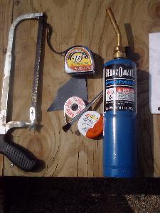
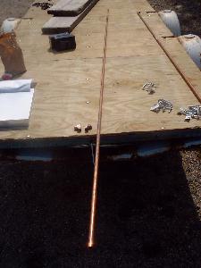
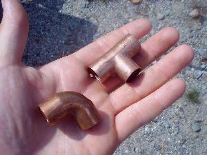
All you need for material is a 10’ piece of ½" Type L (thicker walled) copper water pipe, 1 T fitting and 1 90 degree elbow.
For implements of destruction you will need:
10’ of pipe 2 fittings
Ok, let’s start breaking stuff :o) woohoo!!
I used meters for all the measurements. A lot easier than trying to figure out inches and fractions of inches.
I’ll keep the labeling consistent with that of the calculator. Pay close attention to where the tips of the arrows point in the diagram below. A slight off measurement is not a big deal.
Again, this is for 146 Mhz-
A= 1.47 meters
B= .488 meters (round off to .49)
C= .049 meters (round off to .050)
D= .046 meters
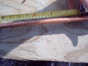
The first step is to cut segment "A".
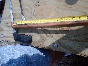
Stick the T-fitting on the end of the 10’ of pipe and shove it all the way in like so and measure from the inside corner.
I use a pencil to mark the segment letter 1.47 meters is about 58 inches
The penciling helps me not to screw up…keeps things simple. Anyway….
.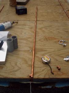
Segment A is now done
The next step is Segment "B". Grab the remainder of the copper pipe use CAUTION not to accidentally grab "A" and cut it…whups.
"B" needs to be .49 meters long. Stick the 90-degree elbow on the end. Measure from the inner corner out to .49 and cut it.
There’s only one more cut to make…again…make sure you don’t cut from "A" or "B".
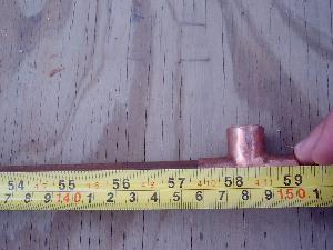
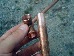
Segment "D"…yes "D". "C" comes later.
The spacing for "D" needs to be .046 meters. I cut a small piece about .044 long from the remaining pipe. I could slide the elbow in or out as needed to get the right measurement.
"D"
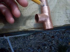
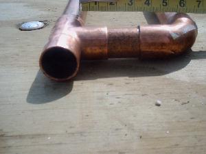
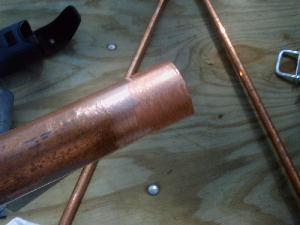
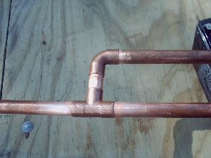
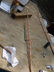
Ok, now take whatever’s left of your remaining pipe and shove it in the bottom of the "T" joint. You should have something like this-
Assembled, but not soldered.
Now’s the time to double-check the measurements.
Alrighty…time to glue this puppy together. You get to practice your plumbing skills.
Pull it apart. Be sure not to get "A" confused with the bottom piece.
You’ll now need to sand the joints. This is absolutely CRUCIAL!!! If you try to solder the pipe and it isn’t shiny, the solder won’t even begin to adhere (stick) to the pipe. Cleanliness is the key when soldering. Shine it right up! Sand inside of the "T" fitting and 90 elbow. Sand the outside of the pipe. Then wipe the dust and geeb off with the rag.
You only need to sand about 2" down the pipe
Now you need to apply the flux. Use the acid brush and wipe flux all over where you’ve shined. Assemble the antenna as you go to prevent dirt intrusion. Notice the smear in the right pic…that’s all the flux you need. Just a light coat.
All together with flux
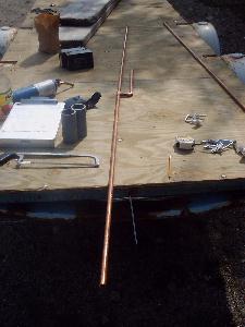
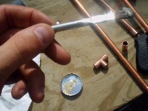
Before you can solder the antenna needs to be elevated a few inches so that you can heat underneath each joint. Make sure that the measurements are still correct and that "B" is parallel with "A". When it’s ready, solder it.
Fire up your propane torch. Pick a joint and start heating from the bottom. Heat the pipe and the fitting. You’ll notice the flux start to liquidize and dribble. This is normal. Hold the solder on the top of the joint. When it starts to melt, remove the torch and quickly run the solder around the joint. You’ll have to do this a couple of times. You might also have to apply a little more heat. The solder will be sucked right into the joint. This is what you want.
Solder everything else the same way.
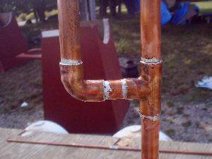
All soldered.
I suggest letting it cool for a while before continuing.
Ok…now it’s time for Segment "C". You could just attach stripped back coax to the feed point. I don’t like doing it that way. I use a SO-239 connector. The SO-239 is what couples to a PL-259.
To the workbench I went and made up the connector.
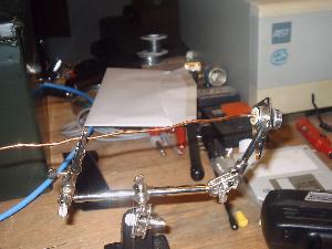
I used a piece of 14 AWG solid copper wire and soldered it into the connector. I used a 140/100 watt soldering gun for this.
Then back to the J-pole. Let’s make Segment "C". Measure up from the inner corner of the "T" joint .050 meters and pencil it. Then sand this area and eyeball across to Segment "B" and sand the same area. Sand the wire where it will contact Segment "A". Wipe them off with the rag. I suggest that you measure again and pencil it so that you solder at the exact measurement.
Now, before you go any further. There are 2 ways to attach the connector. Bolt it or solder it. If you’re doing this for the first time or are new to soldering I suggest you bolt it. If you get the connector TOO HOT you’ll melt the insulator right out of it. Just use a small bolt and drill a hole thru Segment "B" at the .050 mark.
I soldered mine….keep in mind I’ve been doing this stuff for awhile.

For soldering-
Sand a corner of the connector and wipe it.
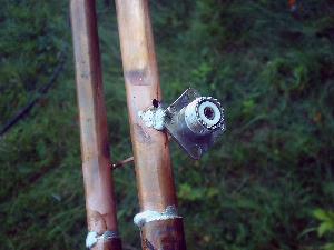
Ok, if you’re bolting the connector go ahead and bolt it. Then you can solder the wire to Segment "A".
If you’re soldering the connector I suggest doing it like the above pic. Wrap the excess wire over Segment "A". This will hold the connector snug on "B".
Spread flux on the wire and on "A". Then solder it just like you did on the fittings.
Then carefully solder the connector to "B". If you melt the snot out of it don’t say I didn’t tell you so.
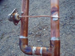
Just snip off the excess wire
Bam Boom
You’ve got a J-pole
73’s and Happy J-polin’
Jaden
www.alpharubicon.com
All materials at this site not otherwise credited are Copyright (c) 1996-2003 Trip Williams. All rights reserved. May be reproduced for personal use only. Use of any material contained herein is subject to stated terms or written permission.