I have been flooded with requests for the General Electric PLL-02A radio conversion to open up a lot of channels above and below the normal 40 CB channels (this works for the old Cobra 148's too). I didn't want to release it to the "General Public" cause I didn't want to flood the "out band" frequencies that overlap the Ham guys on the 10 meter band. But I've seen several of these conversions on radio sites now, and what you do with it is YOUR responsibility!!!!
This conversion is ILLEGAL unless you are a Ham operator licensed to be on these frequencies. Therefore, this is for educational purposes only (add in any other legal garbage that needs to be inserted here at this point. I always feel so stupid having to say that)
So, here goes... It's a very simple conversion.
You need a General Electric 40 channel CB radio with the PLL-02A chipset in it. These radios are about 10 years old and were HUGELY popular so they are turning up at yard sales everywhere now. On the front of the radio it says in small letters (usually right under the power meter), "PLL System". There were some other radios (a few Cobras) that have the PLL chipset in them also, and this conversion will work on them too. It even works on the General Electric Sideband (SSB) model.
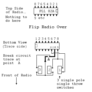
Here is my great schematic drawing (don't laugh, I don't have AutoCAD installed on this machine so I had to use paint shop).

You will be working on the Circuit Trace side of the radio, so you will be looking at the chip upside down (like the lower half of the picture). You will need some hookup wire and three "single throw, single pole" switches (push button, or toggle... either is fine).
Break the circuit trace running from pin 10 (where I have it marked point "A" in the schematic). Run your hookup wires from the chip to the switches as shown. Mount your switches on the outside of the radio case somewhere (plan this in advance cause you will have to do some cutting to the case)...You are done!
Now you have to experiment to figure out what channels you are on as you throw different combinations of switches on each different channel. A frequency counter REALLY comes in handy here since you have 8 possible combinations on each channel, for a total of 320 possible channels!!!
Now... someone is going to get industrious and add a "tuner" circuit in to this so you can make an infinite number of frequencies and half frequencies (including Sideband channels) by "sliding" between frequencies with pots instead of flipping to them with switches. When you get it worked out I would like a copy of the plans with some brief instructions on how you did it (I simply don't have time to do it)
(As a side note: Something in my brain keeps saying there should be a diode between pins 9 and 2... but it drops out of adjustment when you do, so if you have unexpected problems you may want to try running the diode with the cathode side on pin 2)
Warlord

All materials at this site not otherwise credited are Copyright © 1996, 1997, 1998, 1999, 2000 Trip Williams. All rights reserved. May be reproduced for personal use only. Use of any material contained herein is subject to stated terms or written permission.
Return to The Alpha Group Web Page