*Fixing A Fried Tuner*
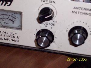
The other night I was playing around with a newly acquired HF radio. It has vacuum tubes on the power amplifier and some extra knobs on front that I’m not familiar with. I read the book about tuning the thing up and commenced to try. I was only getting about 10 watts FWD out of it. According to my tuner’s meter there was 100 watts reflected. I fiddled with the controls a little and poof, a nice puff of smoke rises from the tuner. Great. Opened up the cover and found the inductor rotary switch fried.
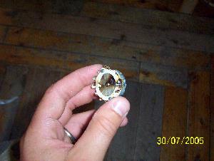
Inductor selector
I’m not familiar with exactly how a tuner works. I know what it does and have a basic concept, but that’s it. So I commenced to peruse the Internet looking for 12 position rotary switches. Found some crappy deals that would cost me $30.00. Finally stumbled across www.action-electronics.com. I found a switch that looked like it’d work so I ordered it. $10.82 cents later it was mine. It took about 4 days to get here from California and finally landed in the mailbox.
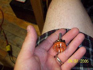
Not good New switch
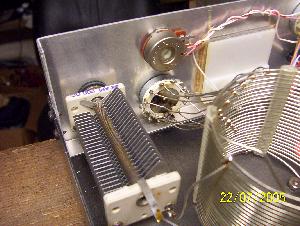
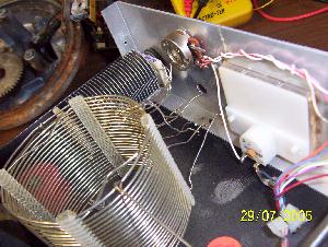
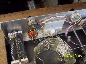
Before desoldering the old switch, I made sure I knew which wires did what. Notice in the left picture the coil. That’s the inductor. The leads going to the switch lengthen or shorten the electrical path of the RF. I have a cheat sheet so I can see that for 80 meters, I need inductor setting "I" so naturally I wanted to keep it the same. I used a multimeter and found inductor A on the switch. Then I looked to see where it connected to the inductor coil and then wrote it down. I went all around the switch and did this, then I desoldered it.
Desoldering wires Toast….literally
While doing this I thought….. " There are 12 inductor selections on the switch, there are only 12 leads running to the switch. Where is the rest of the circuit?" It was late and I wasn’t thinking too good. I found position 1 on the new switch and set that up as inductor A. Then I soldered wires in their respective places.
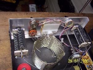
I hooked it up to the radio. No matter what I did, I couldn’t adjust the SWR or reflected power. Hmm…..went to bed.
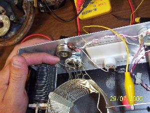
Today the FIL was here and we both looked at it. He said it didn’t make sense either. There was no circuit. Well, it’s hooked up the same way as the other switch! Ok, what gives?? Finally a light snapped….it must have to be grounded. I took a clip lead and attached to the chassis. Then I clipped the other end right to a position on the inductor. I tuned the radio to that band and keyed up. Wallaaa, tuner workee real good now. I wound up soldering a wire to the switch’s supply pin and grounding it. The old switch grounded through it’s chassis, the new does not.
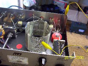
Grounded by clip lead Ground jumper (blue wire)
I used it this afternoon for the statewide net and it worked awesome. $10.82 and little time sure beats $150 for a new tuner.
Jaden
www.alpharubicon.com
All materials at this site not otherwise credited are Copyright © 1996 - 2005 Trip Williams. All rights reserved. May be reproduced for personal use only. Use of any material contained herein is subject to stated terms or written permission.