*RWN Dipole Reception*
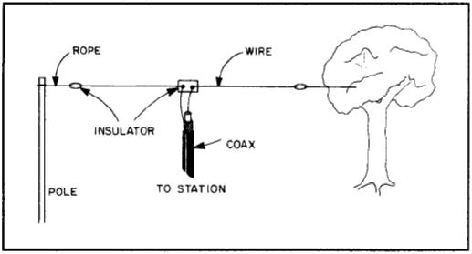
This is a dipole antenna used to receive RWN on a transceiver. An overview of a dipole antenna looks something like this …..
The dipole optimally is one-half wavelength long and suspended at least one-quarter wavelength high. Mathematically, RWN frequency 7.106 MHz yields a half-wavelength of about 66 feet. Thus, each "leg" is 33 feet long and we want to suspend it 33 feet or higher. Now, to assemble the dipole. (Check excellent Rubie articles on soldering and coax.)
The 14-gauge Copper-clad steel wire is cut in half, yielding two 33-foot "leg" wires.
An end-insulator is attached to one end of each of the "leg" wires.
The center-insulator leg-connection prongs are tinned.
The free end of each of the ‘leg’ wires is wrapped snuggly around the center-insulator leg-connection ‘prongs’ and soldered.
Now, let’s go outside and have some fun.
Hopefully, Mother Nature will provide trees to facilitate a center "hoist" point and two lateral hoist points of adequate height, distance, and clearance (some limb pruning was necessary). One caution that comes to mind from researching antennas is "NEVER hang your antenna above power lines".
Our center hoist point was over a tree limb - here’s where the fun begins. We wrapped the twine around an old flip cellphone and threw it over the limb! The sight of that cell phone flying thru the air, over the tree, and crashing down on the other side, was strangely exhilarating. Changed the cellphone for clothesline and pulled the clothesline back over the limb. Attached the center insulator to the clothesline, hoisted the center insulator back up, determined (using twine) that 85 feet of feed-line (from the suspended center-insulator to the transceiver) would be needed, and lowered the center insulator. Note - often it is suggested that the feed-line drop straight down to the ground from the center-insulator. Went back inside, cut 85 feet of coax and soldered PL-259 connectors on both ends. Attached the feed-line to the center-insulator, hoisted it back up, stowed the excess hoist-line and tied it off - Center hoist done.
The two "end" hoists were accomplished with cellphone tosses over trees. The end-insulators were attached to the twine and hoisted up. Excess twine, once hoisted into place, was wrapped up, stowed, and tied to a brick suspended just above the ground so the twine could "ride" with tree-limb movement - looks really neat on a windy day, bricks bobbing up and down!
|
Material |
Cost |
Where Acquired |
|
Budwig HQ-1 center insulator |
6.95 |
|
|
Budwig HQ-2 end insulators (2) |
1.89 |
|
|
14-Gauge Copper-clad Steel wire, 66 ft @ 15 cents per |
9.90 |
|
|
Twine - twisted nylon (#18, 250# test) 300 feet |
1.50 |
Hardware Store |
|
Coax (RG58) Feed Line (17 cents per, I needed 85 ft) |
14.45 |
Radio Shack |
|
PL-259 Connectors (2) |
2.00 |
Radio Shack |
|
One (1) old "Flip" Cell-Phone ( or a $5 slingshot) |
- |
around house |
|
Two (2) bricks |
- |
around house |
|
$ 36.69 |
Oddly enough, visitors don’t even notice this antenna. We drove a ground-rod in the yard just outside the "ham shack" window. When the antenna is not in use, we disconnect it from the transceiver and connect it to the ground-rod outside the house.
Blue skies
Skyjump
www.alpharubicon.com
All materials at this site not otherwise credited are Copyright © 1996 - 2005 Trip Williams. All rights reserved. May be reproduced for personal use only. Use of any material contained herein is subject to stated terms or written permission.