*Vertical Dipole*
simple to construct gain antenna
When I read I read Eli’s article on his dipole made from coax http://www.alpharubicon.com/restricted/radio/bob2antennajaden.htm
It reminded me of an antenna I had seen and made before, that also has great potential.
I am going to describe how to build a coaxially fed vertical dipole. It’s a vertically polarized, gain antenna that you can make and store in your BOV, BOB or at your base of operations/retreat. The diagram I have included here is a bit more complicated than the basic expedient/portable antenna that you can make from just a piece of coax, but it will lead us into more elaborate variations. The simplest coaxial half wave is constructed from a length of coax at least a half-wave at design frequency (remember length in feet = 468/Frequency in MHz), but you could use one continuous piece all the way back to the rig! You begin by removing Ľ wavelength of the outer jacket from the coax, very carefully, without damaging the braid. Then you work the braid a little loose so you are able to slide it down and roll it back over the uncut portion of the jacket. At this point you could string the center conductor up with a piece of twine or other non-conductor and run the other end to your rig with an PL259 or other appropriate connector and operate this as you would a wire dipole. But as with a wire dipole a little trimming and weather proofing is usually best. Because the nature of the braid is to stretch and compact I would measure the length of the exposed center conductor (actually the foam or other insulation is still on it and can be left there!) and stretch or compress the braid so it reaches the same length down over the feed line, taping it in place if necessary. Then I would check the SWR at and around the design frequency and adjust the center conductor and braid lengths as I would a wire dipole. If you are lucky it’s right on, or the SWR gets better as you go lower in frequency, so you don’t have to add any length. The braid and center conductor should be the same length when properly trimmed.
Once you have it trimmed you could add a crimp ring connector or a standard antenna dog-bone insulator to the tip (plan ahead for this when trimming) to make it easy to hang the antenna with a suitable non-conductive line; and at least securely tape the bottom of the braid to the jacket so it’s length won’t change. This should still be fairly flexible and could be coiled and stored in a BOB (depending on what band it’s sized for and assuming it was made from RG58 or Mini8). Of course make sure you don’t coil it any tighter than the coax itself was designed to be coiled or the conductors may "migrate" over time and change the characteristics of the cable. If you don’t need the antenna to be that compact you can use RG8 and wrap the whole thing with electrical tape starting at the bottom and working upward, with maybe a shot of non-conductive caulk or use commercially available Coax Seal or liquid electrical tape at the center to keep water from getting inside the coax. With an RG8 antenna taped up in this manner you could still coil the antenna to easily be stored in the trunk of a car.
For those who want to get more permanent and weather proof, you can mount this antenna into an appropriate sized piece of PVC pipe (spray paint it a subdued color after completion if desired). I would cut the pipe a foot or so longer than the antenna so you will have some separation from the antenna inside and the metal mast you will u-bolt or hose clamp it to. You could give it a blast of spray foam from the bottom (pre test to make sure the foam doesn’t react with the coax) and/or use a crimp connector to bolt the center conductor to the PVC pipe cap at the top to insure the antenna stays in the pipe. For a real commercial looking job I would mount an SO239 to the bottom. You could actually use hollow tubing (in place of the braid) as in the diagram when mounting in PVC pipe, but that would increase the weight. If necessary the assembly could be guyed with non-conductive guys. With a little experimentation and a little more intensive "plumbers delight" assembly you could use a loaded Ham-Stick antenna for the radiator section by mounting it on top of the PVC pipe with just the ground section inside. I’m thinking of 6 to maybe 20 meters being reasonable bands to try this on. In an emergency situation the antenna you build may be limited by what you have on hand, and increasing the range of a Ham-Stick loaded whip may be a viable option.
I built the simple of these several years ago, cut for a specific frequency in the VHF low band, so it was only a little over 10 feet long. I didn’t go as far as to encase it in PVC, I just taped it up well after adding a little coax seal where the braid separated. I put a crimp on ring connector at the top and tied a piece of twine to it and hoisted it into the trees. It got knocked down several times due to storms and falling branches but when I hook it to my MFJ 249 Antenna Analyzer, it’s still resonates where I cut it for. Not bad for a piece of coax I was going to trash. I’ve seen these used on 10 meters and CB, and they are obviously easy to make and great for 2 and 6meters, they would work well for UHF but you could find plans for stacked versions due to the smaller sizes required "up" there. These would also work for the other HF bands; you just need the room to install them!!
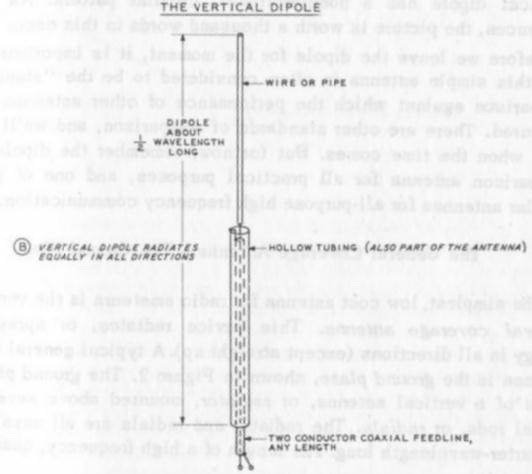
(The diagram is from the book: Simple, Low Cost Wire Antennas for Radio Amateurs, by William I. Orr and Stuart D. Cowan)
www.alpharubicon.com
All materials at this site not otherwise credited are Copyright © 1996 - 2005 Trip Williams. All rights reserved. May be reproduced for personal use only. Use of any material contained herein is subject to stated terms or written permission.